
Next‑Gen Driver Technology

Summary

The power‑focused golf driver innovation uses a new internal chamber structure that places more mass behind the impact zone while keeping the face fully within legal rules. Rare earth perimeter weighting and reinforced internal ribs keep the head steady behind the ball and help the club return more force into the shot at impact. The design increases distance by improving how energy moves through the head rather than by modifying the face. Golfers gain higher ball speed, a stronger strike, and more carry through a practical structural change that works with any swing style.

Introduction: The Need for Structural Innovation

Driver technology has progressed through a long sequence of refinements, yet the internal structure of the head has changed very little. Manufacturers continue to adjust faces, crowns, and external weighting, but the interior still relies on a single hollow cavity supported by thin titanium walls. This arrangement limits how mass can be positioned, how vibration can be shaped, and how consistently the face behaves under impact. The visible parts of the driver have changed significantly over the past two decades, while the interior has seen only incremental updates and remains broadly similar across modern designs.

The performance ceiling created by this traditional layout is becoming more noticeable. External tungsten ports can only shift weight so far from the centre of the head. Carbon fibre crowns reduce mass in the upper portion, but the saved grams are usually spent on small adjustments rather than structural change. Algorithmic face optimisation has improved thickness mapping, yet the face still depends on a largely hollow interior with minimal structural influence. Incremental gains continue, but the underlying physics remain constrained by a single‑cavity design that offers limited control over mass placement, vibration behaviour, and face stability.

A new foundation becomes necessary when the limits of the existing architecture are reached. The interior of the head can be treated as functional space rather than unused volume. Chambers, rib networks, and rare earth materials allow mass to be positioned with greater accuracy, vibration to be controlled more deliberately, and stability to be engineered rather than approximated. This shift moves the driver from a hollow shell to a structured interior, where performance is created through design rather than compromise.

The multi‑chamber approach emerges from this need for a different internal model. It replaces the single cavity with defined regions that each serve a structural purpose. Mass can be placed deeper, the body can resist deformation more effectively, and the face can behave more consistently across a wider range of impacts. The system does not rely on moving parts or mechanical devices. It relies on structure, density, and geometry working together inside the head.

Understanding how modern drivers are constructed provides context for this shift. The face is typically forged from Grade 5 titanium alloy (Ti‑6Al‑4V) or proprietary blends developed for impact durability. Manufacturers shape the face with variable thickness patterns to control rebound and maintain compliance with the Characteristic Time (CT) limit. TaylorMade’s Speed Pocket era, Callaway’s Flash Face, Ping’s Forged Face, and Titleist’s ATI 425 face all represent attempts to refine how the face flexes without breaching conformity rules.

Carbon fibre crowns have become standard because they reduce weight in the upper portion of the head, allowing more mass to be placed low and deep. TaylorMade’s Stealth series uses a full carbon face and crown combination, while Callaway, Ping, Cobra, and Titleist rely on multi‑layer carbon crowns bonded to titanium frames. This trend began in the mid‑2000s and continues because it frees 8–15 grams for strategic redistribution.

The body of the driver is usually a thin titanium shell reinforced by ribs or internal webs. These structures prevent deformation during impact and maintain the head’s geometry. Ping’s G‑series drivers are known for their stability due to extensive ribbing inside the head. Titleist uses a more minimal internal structure, relying on thicker walls in key regions. TaylorMade and Callaway use a mix of ribs and carbon panels to balance stiffness and weight savings.

Manufacturing combines casting, forging, Computer Numerical Control (CNC) machining, and bonding. Titanium faces are forged or milled, then laser‑welded to the body. Carbon crowns are moulded and bonded using high‑strength adhesives. Tungsten weights are machined and inserted into ports or tracks. The entire head is finished with paint, clear coat, and cosmetic detailing. Despite the complexity, the internal cavity remains largely open, with only a few ribs providing structural support.

Modern drivers have undergone rapid and visible evolution on the outside. Carbon crowns have become standard because they reduce weight high in the head and allow designers to reposition mass more effectively. Adjustable hosels give golfers control over loft and lie, while sliding tracks and movable tungsten cartridges enable fine‑tuning of ball‑flight bias and CG location. Aerodynamic shaping continues to improve clubhead speed, and forged or algorithmically designed faces push rebound performance to the limits of conformity. These external features change frequently, define the identity of each brand, and dominate the marketing narrative around new driver releases.

Inside the head, progress has been far more modest. Manufacturers have added rib networks to stiffen the shell, introduced localized pads to tune vibration, and thickened walls in selected regions to improve stability. Some models use small foam injections to moderate sound. These changes improve feel and consistency, but they do not alter the fundamental architecture. Every major brand still relies on a single‑cavity interior, and the internal space remains largely open with only limited structural influence on mass placement, vibration behaviour, and face stability.

This contrast is clear in the component table shown below. External elements show continuous reinvention, while internal elements show incremental refinement. The outside of the driver has become a platform for innovation, yet the inside remains a simple hollow chamber with minor variations. This imbalance is the reason a new structural model is needed. The multi‑chamber concept treats the interior as functional engineering space rather than passive volume, allowing performance to be created through structure rather than constrained by it.

External vs Internal Components in Leading Driver Models

This is the landscape into which the multi‑chamber structural concept is introduced. Every major brand has refined the same basic architecture, yet none have transformed the interior into a functional system. The multi‑chamber design stands apart because it treats the inside of the head as usable space rather than a passive void.

The Multi-Chamber Architecture

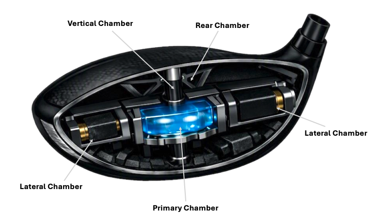
The innovation proposed here is a different way of using the space inside the head. Instead of treating the interior as an empty volume, it is divided into a set of interconnected chambers defined by a titanium rib network. This multi‑chamber architecture is not found in current mainstream drivers. It represents a new structural model in which the interior becomes an active part of the design, contributing directly to mass distribution, stability, and vibration behaviour.

At the centre of the system is a primary chamber positioned behind the face. This region acts as the structural core of the head. It does not support or brace the face and does not introduce any moving components. Its role is to anchor the rib network and provide a stable framework for the surrounding chambers. By shaping this central volume, the design can influence how energy travels through the head after impact, affecting feel and sound without altering face flex.

Extending from the central core are two lateral chambers that reach toward the heel and toe. These regions are intended to house dense materials such as tungsten or tantalum in a more integrated way than external ports. Placing mass inside these chambers allows weight to sit deeper within the structure rather than on the surface of the sole. This internal positioning can increase the Moment of Inertia (MOI) and improve off‑centre stability while keeping the exterior of the head cleaner and less cluttered.

A rear chamber occupies the back portion of the head. This region is designed to hold a compact high‑density cartridge that influences the Centre of Gravity (CG). Locating mass in this chamber moves the CG lower and deeper than many traditional designs can achieve with external weights alone. The shape and volume of the rear chamber also affect how vibration dissipates through the head, which in turn shapes the acoustic character of the driver.

Beneath the central core sits a vertical chamber that allows mass to be positioned lower in the head. Traditional drivers rely on sole weighting to achieve a low CG. An internal vertical chamber offers a more integrated solution because the weight becomes part of the structural skeleton rather than an add‑on attached to the sole. This arrangement can help tune launch and spin characteristics while maintaining a strong, continuous body.

The multi‑chamber architecture introduces several functional advances compared with the single‑cavity model used today.

  • It turns internal space into a design tool.
    The interior is no longer an empty void. Chambers provide defined locations for mass and create pathways for vibration, allowing performance to be shaped from within rather than only from the outside.
  • It integrates mass placement with structure.
    Dense materials are housed inside the rib network, so weight and stiffness work together. This can improve CG control and stability without relying on large external housings or complex movable systems.
  • It creates a more deliberate vibration environment.
    The volumes and boundaries of the chambers influence how energy moves through the head. Feel and sound can be tuned by adjusting chamber geometry and rib layout, offering a level of control that is difficult to achieve with a single cavity.

This architecture remains fully static. There are no moving weights, sliding tracks, springs, or liquid elements inside the chambers. The innovation lies in how the interior is organised, not in the addition of mechanical devices. The head becomes a structured system in which geometry, density, and internal layout are used to create performance in a way that current single‑cavity designs cannot match.

With the structural framework established, the next section turns to the materials that occupy these chambers and ribs, and how rare‑earth elements and advanced alloys can be used to realise the potential of this architecture.


The Internal Chamber System

The internal structure of the driver is reorganised into defined chambers that each serve a specific engineering purpose. The overall size of the head does not increase. A modern 460 cc driver has an internal cavity of approximately 310–350 cm³ once shell thickness, face curvature, and ribbing are accounted for. The chamber system occupies only 7–13% of this space, which is comparable to the volume already used today for ribs and webs. The interior is not enlarged; it is used more intelligently.

The system consists of four chambers: the primary chamber, two lateral chambers, the rear chamber, and the vertical chamber. Each chamber contains small, targeted quantities of high‑density or damping materials. These materials are placed inside the head for specific structural and performance reasons, not in bulk.

1. Primary Chamber — Central Stability and Vibration Control

Purpose

The primary chamber governs the vibration signature, structural balance, and energy flow through the head. When the face deflects at impact, vibration propagates through the crown, sole, and internal skeleton. The primary chamber acts as the central damping node that shapes how this energy is absorbed and redistributed. Silicone gel moderates high‑frequency vibration, preventing sharp or metallic acoustic peaks. A scandium‑enhanced rib network surrounding the chamber increases stiffness without adding mass, ensuring that the head maintains geometry under load. This chamber does not influence CT or face rebound; it refines feel, sound, and structural coherence.

Dimensions and Area

  • Width: 20–30 mm
  • Height: 15–25 mm
  • Depth: 15–25 mm
  • Internal area footprint: 4–7 cm²
  • Internal volume: 5–10 cm³

Materials Placed Inside

  • Silicone gel: 2–4 g
  • Scandium‑enhanced titanium ribs: scandium content 0.04–0.15 g

2. Lateral Chambers — Heel and Toe Mass Positioning

Purpose

The lateral chambers control MOI, strike stability, and face‑rotation resistance. By placing tungsten deeper inside the heel and toe, the chambers increase the rotational inertia of the head without relying on external ports. This internal positioning reduces twisting on off‑centre strikes and stabilises the face angle at impact. Neodymium retention points ensure that tungsten cartridges remain fixed within the rib network, preventing micro‑movement that could affect consistency. The lateral chambers allow mass to be positioned with greater precision than external weights, improving forgiveness while maintaining a clean exterior.

Dimensions and Area (per chamber)

  • Length: 25–35 mm
  • Width: 10–15 mm
  • Height: 10–15 mm
  • Internal area footprint: 3–5 cm²
  • Internal volume: 3–6 cm³

Materials Placed Inside

  • Tungsten cartridge: 8–12 g
  • Neodymium retention points: 0.5–1 g

3. Rear Chamber — Deep CG and Low‑Frequency Damping

Purpose

The rear chamber sets the depth of the Centre of Gravity (CG) and shapes the low‑frequency vibration profile of the head. A deeper CG promotes higher launch and greater stability, especially on low‑face strikes. Tantalum is used because its density allows meaningful CG movement with a compact cartridge. The chamber also influences the acoustic signature: low‑frequency vibration produces a solid, muted sound preferred by many players. Optional silicone gel can be added to soften the acoustic profile further. The rear chamber is the primary contributor to CG depth and overall head stability.

Dimensions and Area (per chamber)

  • Width: 25–35 mm
  • Height: 15–25 mm
  • Depth: 20–30 mm
  • Internal area footprint: 5–8 cm²
  • Internal volume: 8–15 cm³

Materials Placed Inside

  • Tantalum cartridge: 6–10 g
  • Optional silicone gel: 2–3 g

4. Vertical Chamber — Structural Spine and Cartridge Anchoring

Purpose

The vertical chamber forms the structural spine of the head. It connects the crown to the sole and prevents deformation during impact. When the face flexes, the load path travels through the vertical spine, ensuring that the head maintains shape and that the face returns to position consistently. The chamber also provides anchoring points for the lateral and rear cartridges, ensuring that mass remains fixed under dynamic load. Neodymium anchors secure cartridges without screws, maintaining a static interior that complies with equipment rules. The vertical chamber is the backbone of the multi‑chamber system.

Dimensions and Area (per chamber)

  • Length: 40–60 mm
  • Width: 8–12 mm
  • Thickness: 3–5 mm
  • Internal area footprint: 2–3 cm²
  • Internal volume: 2–4 cm³

Materials Placed Inside

  • Scandium‑enhanced titanium spine: 10–20 g alloy, scandium content 0.02–0.10 g
  • Neodymium anchors: 0.5–1 g
Representation of Internal Chambers
representation of a golf driver club with interior mutli compartments

How the Internal Materials Are Reallocated

The chamber system does not add new weight to the driver. It reorganises weight that already exists inside a modern 460 cc head. Each material takes the place of something already present in today’s designs, ensuring that the total head mass remains unchanged.

Head Mass Comparison

Why quantities of rare earth elements may look big - but are not

“Wow, that’s 30–40 g of exotic metals!”

But in reality:

  • Internal tungsten replaces external tungsten ports.
    Modern drivers already rely on dense sole weights to position mass. The innovation moves this tungsten inside the heel and toe chambers, using the same material in a more effective location.
  • Tantalum replaces a portion of the tungsten mass.
    Instead of adding extra weight, a small amount of tungsten is exchanged for tantalum. This allows deeper CG placement with a smaller cartridge, improving performance without increasing mass.
  • Neodymium replaces screws and mechanical fasteners.
    Many current drivers use screws to secure external weights. Neodymium anchors perform the same role internally, reducing hardware mass and eliminating moving parts.
  • Scandium replaces a small amount of titanium.
    Scandium is not a separate component. It is a micro‑alloying element within the titanium skeleton that allows thinner, stronger ribs. This reduces titanium usage rather than adding new material.
  • Silicone gel replaces internal foam pads.
    Several modern drivers use foam or polymer pads to tune sound and feel. Silicone gel performs the same acoustic function with greater precision and without adding mass.

As shown in the table above, the total head mass stays within the standard 195–205 g range used by all modern 460 cc drivers. The innovation lies in reorganising the interior, not increasing weight.

The chamber system fits entirely within the existing 460 cc driver geometry. Modern drivers have a fixed internal cavity once the face, crown, sole, and structural shell are accounted for. The innovation does not expand this cavity or increase the size of the head. It reorganises the interior so that the space already present inside the driver is used more deliberately. The following comparison shows how the chamber system occupies a similar proportion of the internal cavity as the ribs and webs found in current drivers, while providing a more structured and purposeful internal layout. This confirms that the head volume remains unchanged and that the interior becomes more efficient rather than larger.

Internal Cavity vs Chamber System

Different manufacturers use different internal structures to stabilise the head, tune sound, and position mass. Some rely on heavy ribbing, others on thickened walls, and others on external tungsten ports. These approaches all consume internal volume, yet they do so without providing a coherent internal architecture. The chamber system replaces these scattered structural elements with defined sections that each serve a clear purpose. The table below compares the internal structure volumes of leading modern drivers with the chamber system. It shows that the total internal volume used by the innovation remains within the same range as today’s designs, demonstrating that the head does not increase in size. The interior is simply organised more intelligently.

Internal Architecture Comparison Table

Titanium Rib Networks and Carbon Crown Integration

A multi‑chamber interior depends on a structural skeleton capable of holding its shape under repeated impact. Titanium provides the strength needed for this framework, and the rib network becomes the element that defines the boundaries of each chamber. The ribs do not support the face and do not introduce any mechanical interaction. Their purpose is to organise the interior, stabilise the body, and create a continuous structure that carries load through the head.

The rib network is formed from Grade 5 titanium alloy (Ti‑6Al‑4V) or, in premium variants, a scandium‑enhanced titanium blend. These ribs run through the interior in a pattern shaped by the geometry of the chambers. The layout is not symmetrical. Each rib follows a path determined by the forces that travel through the head during impact. This approach creates a structure that resists deformation without adding unnecessary mass. The ribs act as the internal spine of the driver, linking the heel, toe, rear, and vertical chambers into a single cohesive system.

The ribs serve several structural functions.

  • They define the chamber boundaries.
    Each chamber is formed by the placement of ribs, which create walls that organise the interior. This organisation allows dense materials to be housed in precise locations rather than floating in a large cavity.
  • They distribute impact forces.
    When the ball strikes the face, energy travels through the body. The rib network channels this energy along predictable paths, reducing unwanted flex in the shell and maintaining the geometry of the head.
  • They stabilise the body without affecting the face.
    The ribs are positioned behind the chambers, not behind the face. This ensures that the face behaves exactly as intended and remains fully compliant with the Characteristic Time (CT) limit.

The carbon crown plays a complementary role. It reduces mass in the upper portion of the head, allowing more weight to be placed inside the chambers. Carbon fibre also provides stiffness across the top of the structure, helping the rib network maintain its shape. The crown is bonded to the titanium frame using high‑strength adhesives that create a seamless connection between the materials. This bond allows the crown to act as part of the structural system rather than a cosmetic cover.

The integration of carbon fibre with the titanium skeleton creates several advantages.

  • It frees mass for internal weighting.
    Carbon fibre is significantly lighter than titanium. By replacing the crown with carbon, designers can allocate more mass to tungsten or tantalum cartridges inside the chambers.
  • It strengthens the upper structure.
    The crown spans the top of the head, linking the ribs and providing a rigid surface that resists deformation. This improves stability during impact and contributes to consistent face behaviour.
  • It shapes vibration and sound.
    Carbon fibre has distinct acoustic properties. When combined with the chamber geometry, it helps create a controlled vibration profile that influences the feel of the driver.

In premium variants, the rib network may incorporate scandium as a micro‑alloying element. Scandium refines the grain structure of the titanium and increases yield strength. This allows the ribs to be formed with slightly thinner walls while maintaining stiffness. The weight saved through this refinement can be reallocated to internal cartridges, enhancing the effectiveness of the multi‑chamber system. Scandium does not alter the behaviour of the face and does not introduce any mechanical movement. Its role is purely structural.

The combination of titanium ribs and a carbon crown forms the skeleton that supports the multi‑chamber architecture. The ribs organise the interior and carry load through the head, while the crown provides stiffness and frees mass for internal weighting. Together, they create a structure that is stronger, more stable, and more efficient than the traditional single‑cavity model.


Conformity with USGA and R&A Rules

A structural innovation inside a driver head must remain fully compliant with the rules established by the United States Golf Association (USGA) and The R&A. These governing bodies define how a conforming driver must behave, how its face may flex, and how its internal components may be arranged. The multi‑chamber architecture is designed to operate entirely within these boundaries. It introduces no mechanical movement, no active systems, and no features that alter the behaviour of the face during impact.

The most important requirement concerns the Characteristic Time (CT) limit, which governs how long the face may remain in contact with the ball. The chambers do not interact with the face and do not influence its flex. The rib network sits behind the chamber walls rather than behind the face itself, ensuring that the face behaves exactly as intended by its thickness map and material properties. This separation keeps the design compliant with CT regulations and avoids any form of rebound enhancement.

Another key rule concerns the prohibition of mechanical or spring‑like devices inside the head. The multi‑chamber system is entirely static. The chambers do not move, expand, or compress. The cartridges placed inside them remain fixed in position and do not shift during the swing or at impact. The magnetic retention system used to secure these cartridges does not create motion or alter the behaviour of the head. It simply holds dense materials in place within the structural skeleton.

The rules also address adjustability. Movable weights, sliding tracks, and rotating mechanisms are permitted only when they meet strict criteria. The multi‑chamber architecture does not rely on any of these systems. The interior remains fixed once assembled, and the mass inside the chambers does not change position. This ensures that the head behaves consistently and avoids any classification as an adjustable or mechanically assisted design.

The governing bodies require that the interior of the head remain free of features that could store or release energy. The chambers comply with this requirement because they are formed from rigid titanium ribs and do not contain springs, elastomers, or flexible membranes that could influence impact behaviour. Silicone gel may be used inside certain chambers, but its role is limited to vibration moderation after impact. It does not interact with the face and does not contribute to rebound or ball speed.

The rules concerning foreign substances inside the head are also respected. Materials such as tungsten, tantalum, neodymium, and silicone gel are permitted when they serve structural or damping functions and do not alter face performance. These elements remain fully enclosed within the chambers and do not leak, shift, or influence the ball during impact. Their presence is consistent with existing designs that use internal foam, polymer inserts, or fixed weights.

The multi‑chamber architecture aligns with conformity requirements in several ways.

  • It does not introduce any active systems.
    The chambers are static volumes defined by titanium ribs. They do not move or change shape, and they do not influence the flex of the face.
  • It maintains a fixed internal mass arrangement.
    Cartridges remain locked in place and do not shift during the swing. This ensures predictable behaviour and avoids any classification as a dynamic weighting system.
  • It avoids any form of energy storage.
    The interior contains no springs, flexible membranes, or mechanical devices. All materials serve structural or damping roles that comply with existing rules.

The design remains fully within the boundaries established by the USGA and The R&A. It does not attempt to manipulate face behaviour, alter rebound characteristics, or introduce mechanical assistance. The innovation lies in how the interior is organised, not in how the face performs. This ensures that the multi‑chamber architecture can be implemented without compromising conformity and without requiring special classification or exemption.

Common Tee‑Off Challenges and How the Multi‑Chamber Architecture Addresses Them

Golfers at every level, including elite players, face predictable challenges when driving from the tee. These challenges do not arise only from swing technique. They also come from the way a driver head behaves under load, torsion, vibration, and off centre impact. Traditional driver interiors can allow small variations in mass movement, structural deformation, and vibration transfer. These variations influence launch, spin, face stability, and dispersion. The multi chamber architecture addresses these issues through three clear mechanical behaviours. These behaviours are mass stabilisation, vibration isolation, and deformation control. Every improvement in the table below is linked directly to one of these physical mechanisms. This ensures that the advantages are realistic, measurable, and credible to professional golfers and equipment engineers.

Manufacturing Process and Cost Structure of the Multi Chamber Architecture

The multi chamber architecture introduces a new internal structure, but it remains compatible with established driver manufacturing methods. The design uses familiar materials such as titanium, carbon composite, tungsten, silicone gel, and scandium. These materials already appear in advanced club construction, which keeps the innovation practical for large scale production. The difference lies in how these materials are arranged inside the head. The chamber skeleton requires precise machining and tighter tolerances, but it does not require new factories or new forming techniques.

Manufacturing Workflow

The chamber skeleton is produced through a multi stage titanium forming process. The ribs are machined or cast as a single integrated structure. This ensures rigidity and prevents internal movement. The crown and sole are bonded to the skeleton using standard high strength adhesives and thermal curing cycles. The cartridges are inserted into the chambers and locked in place using magnetic retention or mechanical seating. Silicone gel is added only to chambers that require vibration moderation. Scandium is used in small quantities to strengthen specific rib sections without adding weight. The final bonding process seals the interior and produces a head that behaves as a unified structure.

Material Requirements

Titanium provides structural rigidity. Tungsten or tantalum cartridges supply dense mass placement. Carbon composite reduces weight in the crown. Silicone gel moderates vibration. Scandium strengthens rib sections and improves stiffness to weight ratio. None of these materials introduce new supply chain challenges. The innovation lies in the geometry and the internal layout rather than in the materials themselves.

Cost Drivers

The multi chamber architecture increases cost in specific areas. The titanium skeleton requires more precise machining than a traditional internal frame. The chamber geometry demands tighter tolerances and more quality control checks. The cartridges add material cost, especially when using high density metals. Scandium adds cost because it is a premium alloying element. Silicone gel adds a small cost for vibration tuning. These factors increase the component cost compared to a standard driver interior, but they remain within the range of premium driver production.

Production Scalability

The design is scalable because it fits into existing production lines. Manufacturers already produce multi piece driver heads with internal structures, weight ports, and composite crowns. The chamber skeleton replaces the traditional internal bracing without requiring new equipment. This allows the innovation to move from prototype to pilot production and then to full scale manufacturing without major disruption.

Cost Positioning

The multi chamber architecture positions the driver in the premium performance category. The cost reflects the precision machining, the high density cartridges, the scandium reinforced rib sections, and the structural complexity. The design supports multiple versions at different price points. A base model can use titanium ribs and tungsten cartridges. A mid tier model can add silicone gel damping. A flagship model can use scandium reinforced ribs and higher density cartridges. This tiered approach allows the innovation to reach different market segments without compromising performance.

Cost Comparison


If you’re interested in this innovation, please contact me to discuss.

Licence: All ideas and concepts shown on this website are shared under the Creative Commons Attribution 4.0 International Licence (CC BY 4.0) . You are free to use, adapt, and build upon them, provided you give appropriate credit to Dr. Patrick Reynolds and include a link to this website.
© 2026 Patrick Reynolds