
FlowLogic
A New Computational Domain for Next Generation Data Centres

Summary

FlowLogic introduces a computational substrate in which computation emerges from continuous dynamics, field‑guided evolution, and high‑density interaction rather than discrete switching. It expands the computational landscape by enabling forms of optimisation, multimodal fusion, and adaptive behaviour that conventional CMOS cannot express, yet it is not a replacement for CMOS. The most practical pathway is a hybrid FlowLogic–CMOS architecture, where FlowLogic provides continuous, energy‑efficient, field‑driven computation and CMOS supplies precision arithmetic, deterministic control, and digital interfacing. This combination supports classes of systems that neither substrate can achieve alone, from embedded adaptive controllers to sustainable data‑centre architectures with dramatically reduced thermal and water demands. FlowLogic therefore represents not a successor to CMOS but a complementary computational domain that aligns computation more closely with the structure and dynamics of real‑world processes.

Introduction

For decades, progress in computing has been driven by a single organising principle: make transistors smaller, pack them more densely, and switch them faster. This approach has delivered extraordinary gains, but it is now constrained by the physics of the nanoscale. Leakage currents, quantum tunnelling, heat density, and interconnect delays impose hard limits on further shrinking, while manufacturing has become increasingly fragile and resource‑intensive. Horizontal extensions of the paradigm—chiplets, 3D stacking, advanced packaging, and high‑bandwidth memory—improve bandwidth and density but do not change the underlying computational model or its thermodynamic cost.

At the same time, the rise of large‑scale AI has exposed the environmental and infrastructural limits of switching‑based architectures. Modern accelerators generate extreme thermal loads, require vast electrical and water resources, and concentrate compute in regions with robust cooling infrastructure. These pressures reveal a widening mismatch between the demands of emerging applications and the constraints of the switching paradigm.

FlowLogic addresses this gap not by extending CMOS, but by introducing a complementary computational substrate grounded in continuous dynamics, field‑guided evolution, and interaction‑dense behaviour. It reorganises established physical principles into a system where computation emerges from geometry and flow rather than discrete transitions. FlowLogic does not replace CMOS; instead, it expands the computational landscape. CMOS remains unmatched in precision arithmetic, deterministic control, and digital interfacing, while FlowLogic excels in domains where computation aligns with continuous evolution, multimodal fusion, and adaptive physical behaviour.

The most practical and powerful path forward is therefore a hybrid FlowLogic–CMOS architecture. By combining continuous field‑driven computation with digital precision and control, hybrid systems enable classes of capabilities that neither substrate can achieve alone—from real‑time embodied intelligence to sustainable data‑centre architectures with dramatically reduced thermal and water demands. This shift marks the emergence of a broader computational ecosystem, where FlowLogic provides a new domain of physical computation that complements, rather than competes with, the switching‑based foundations of modern computing.

Taken together, these pressures define a landscape in which no single architecture can meet all emerging demands. The limits of CMOS, the incremental extensions of the industry roadmap, the emergence of flow‑based substrates such as FlowLogic, and the practical advantages of hybrid FlowLogic–CMOS systems now coexist as parallel technological pathways. The table below summarises these four domains, highlighting their assumptions, constraints, and the opportunities they open for future computation.

Why CMOS Cannot Scale Further

The limits facing CMOS today arise from physical laws rather than engineering shortcomings. As devices approach atomic dimensions, the mechanisms that once enabled exponential scaling now impose hard ceilings on switching‑based architectures.

  • Quantum Limits at Atomic Dimensions. At gate lengths near 2 nm, insulating layers become only a few atoms thick. Electrons tunnel through these barriers, producing leakage currents that destabilise logic levels and increase static power. This tunneling is a fundamental quantum effect, not a fabrication defect (Kumari, 2024).
  • Interconnects Now Dominate System Performance. Even where transistors remain functional, the wiring between them has become the primary bottleneck. Resistance and capacitance in nanoscale metal lines slow signal propagation and dissipate more energy than the switching events themselves. System level performance is now constrained by interconnect geometry, not transistor count (Valasa, et al. 2026).
  • Thermal Density Exceeds Practical Cooling. Switching requires forcing electrons across potential barriers, and each transition generates heat. As density increases, thermal flux rises faster than cooling systems can remove it. Modern chips already operate near the limits of practical heat dissipation, making further increases in switching frequency or density unsustainable (Pop and Goodson, 2024).
  • Escalating Manufacturing Complexity and Cost. Advanced nodes require extreme ultraviolet lithography, multi patterning, and atomic scale defect control. These processes demand unprecedented capital expenditure and yield diminishing returns. The cost per transistor is no longer decreasing, breaking the economic foundation of Moore’s Law (Pulickal & D’Costa, 2024; Valasa, et al. 2026).
  • Material and Supply Chain Fragility. Modern semiconductor fabrication depends on rare earth elements and specialized materials concentrated in a few regions. This creates systemic vulnerability as demand grows and supply chains tighten (Ekatpure, 2022).

What New Systems Actually Need

Emerging computational systems—embodied AI, autonomous robotics, continuous perception, and adaptive control—operate in dynamic environments where computation must evolve alongside the world. These workloads expose requirements that switching‑based architectures cannot meet. These include the following:

  • Continuous, Real Time State Evolution. Embodied and interactive systems require continuous updates to internal state as sensory conditions change. Discrete, clocked transitions introduce latency and break the continuity needed for real time adaptation (Nathan, 2023; Zhang et al., 2025).
  • High Bandwidth Multimodal Fusion. Modern agents integrate visual, tactile, auditory, and proprioceptive signals simultaneously. This demands architectures capable of sustaining large, parallel data flows with minimal overhead. Interconnect limited CMOS systems struggle to support such bandwidth (Liu et al., 2024).
  • Geometry Aligned Computation. Tasks such as spatial reasoning, constraint satisfaction, and physical interaction benefit from computation that reflects geometric structure directly. Embodied intelligence research shows that physical layout and continuous dynamics contribute to computation itself (Sun et al., 2024).
  • Adaptive Behavior Under Uncertainty. Real world environments are unpredictable. Systems must modify internal pathways and response patterns without halting or reinitializing. This requires substrates that can reconfigure behavior through changes in fields, weights, or potentials rather than discrete instruction sequences (Zhang et al., 2025).
  • Extreme Energy Efficiency for Continuous Operation. Robotics and autonomous systems operate under strict power budgets. Energy must scale with the complexity of the physical transformation being performed, not with the number of binary transitions. Switching based architectures impose high energy costs for continuous workloads (inferred from Liu et al., 2024; Sun et al., 2024).
  • Native Support for Parallelism and Interaction. Emergent behaviors arise from many interacting processes running simultaneously. Architectures must support large numbers of concurrent operations without global synchronization or clock driven sequencing (Liu et al., 2024).

FlowLogic — What It Actually Is

FlowLogic is a field‑guided, geometry‑defined computational substrate that replaces discrete switching with continuous electron dynamics. Instead of forcing electrons through binary transitions, FlowLogic shapes their movement through controlled potentials, nanoscale channels, and interaction regions. Computation emerges from how electrons distribute, propagate, and transform within these structures—similar to physical neural networks, diffusive memristive systems, and wave‑based computing platforms (Shastri et al., 2021).

FlowLogic is not a metaphor or abstraction. It is a physical architecture with defined materials, dimensions, and operating parameters. Its behavior is determined by geometry and fields, not by switching events.

1. Physical Substrate and Materials

FlowLogic devices are built on a multilayer stack designed to support controlled electron flow at low voltages. A typical implementation uses:

  • Substrate: silicon, glass, or sapphire
  • Channel materials: oxide semiconductors (e.g., IGZO, TiO₂, HfO₂) or conductive polymers (e.g., PEDOT:PSS)
  • Field shaping electrodes: patterned metal layers (Al, Cu, Au)
  • Dielectric layers: SiO₂, HfO₂, or polymer dielectrics
  • Optional high mobility layers: graphene or other 2D materials for enhanced flow control

These materials are chosen because they support diffusive, nonlinear, and field‑responsive electron transport, which is essential for continuous computation (Zhou et al., 2021).

2. Geometry and Dimensions

FlowLogic computation is defined by geometry. The physical layout determines how electrons move, interact, and stabilise into meaningful states.

Typical dimensions:

  • Flow channels: Width: 50–200 nm Length: 0.5–5 µm Depth: 20–80 nm
  • Dynamic state regions: Circular or polygonal zones Diameter: 200–800 nm
  • Field shaping electrode pitch: 100–300 nm
  • Inter region spacing: 200–600 nm

These dimensions are deliberately larger than cutting‑edge CMOS, enabling fabrication without EUV lithography while still supporting nanoscale electron dynamics.

3. Core Structural Components

FlowLogic consists of three interacting physical structures:

a) Field shaping structures

Electrodes embedded above or below the channels generate controlled potential landscapes. By adjusting these fields, the system can:

  • Redirect flows
  • Modulate signal strength
  • Create attractor basins
  • Impose constraints
  • reconfigure computational behaviour

This mechanism replaces instruction‑driven control with geometry‑driven programmability (Shastri et al., 2021).

b) Flow channels

These nanoscale conduits guide electrons along defined paths. Their shape and material properties determine:

  • Diffusion rate
  • Nonlinear response
  • Interference patterns
  • Signal splitting or merging

Channels implement operations such as filtering, integration, and transformation as part of the physical flow.

c) Dynamic state regions

These are interaction zones where flows converge, accumulate, or stabilise. They function as:

  • Transient memory
  • Attractor states
  • Pattern formation regions
  • Nonlinear mixing zones

Diffusive memristive research shows that such regions naturally encode history and adaptation (Zhou et al., 2021).

4. Operating Conditions

FlowLogic operates under low‑energy, continuous conditions:

  • Voltage: 0.1–0.5 V
  • Current: nA–µA
  • Power density: <1 W/cm²
  • Temperature: ambient (no active cooling required)
  • Signal propagation: 1–50 ns across typical channel lengths

These values reflect the fact that FlowLogic does not force electrons across barriers; it guides them along energetically favourable paths (Roy et al., 2019).

5. Fabrication Pathway

FlowLogic can be fabricated using processes already available in standard semiconductor and thin‑film manufacturing:

  • Photolithography (no EUV required)
  • Thin film deposition (ALD, sputtering, evaporation)
  • Soft lithography for polymer channels
  • Back end of line compatibility with CMOS

This makes FlowLogic a practical post‑CMOS architecture rather than a speculative one.

6. Programming Model

FlowLogic is programmed by shaping fields and geometry, not by executing instruction sequences.

Programming involves:

  • Setting electrode potentials
  • Configuring channel connectivity
  • Defining attractor landscapes
  • Adjusting flow constraints
  • Tuning nonlinear response regions

This creates a field‑defined computational graph, where the physical layout is the algorithm (Sun et al., 2024).


Internal Architecture

FlowLogic Architecture is built as a multilayer nanoscale system in which electron flow is shaped, guided, and transformed by controlled fields and geometric constraints. Computation emerges from the physical evolution of charge distributions rather than from discrete switching events. This section describes the internal structure of FlowLogic in detail, showing how each layer contributes to the overall computational behaviour and how the system achieves continuous, field‑defined operation grounded in experimentally demonstrated principles (Shastri et al., 2021; Zhou et al., 2022).

FlowLogic’s internal architecture is therefore not an abstract model but a physical computing medium, where geometry and fields are the algorithm.

Layered Physical Stack

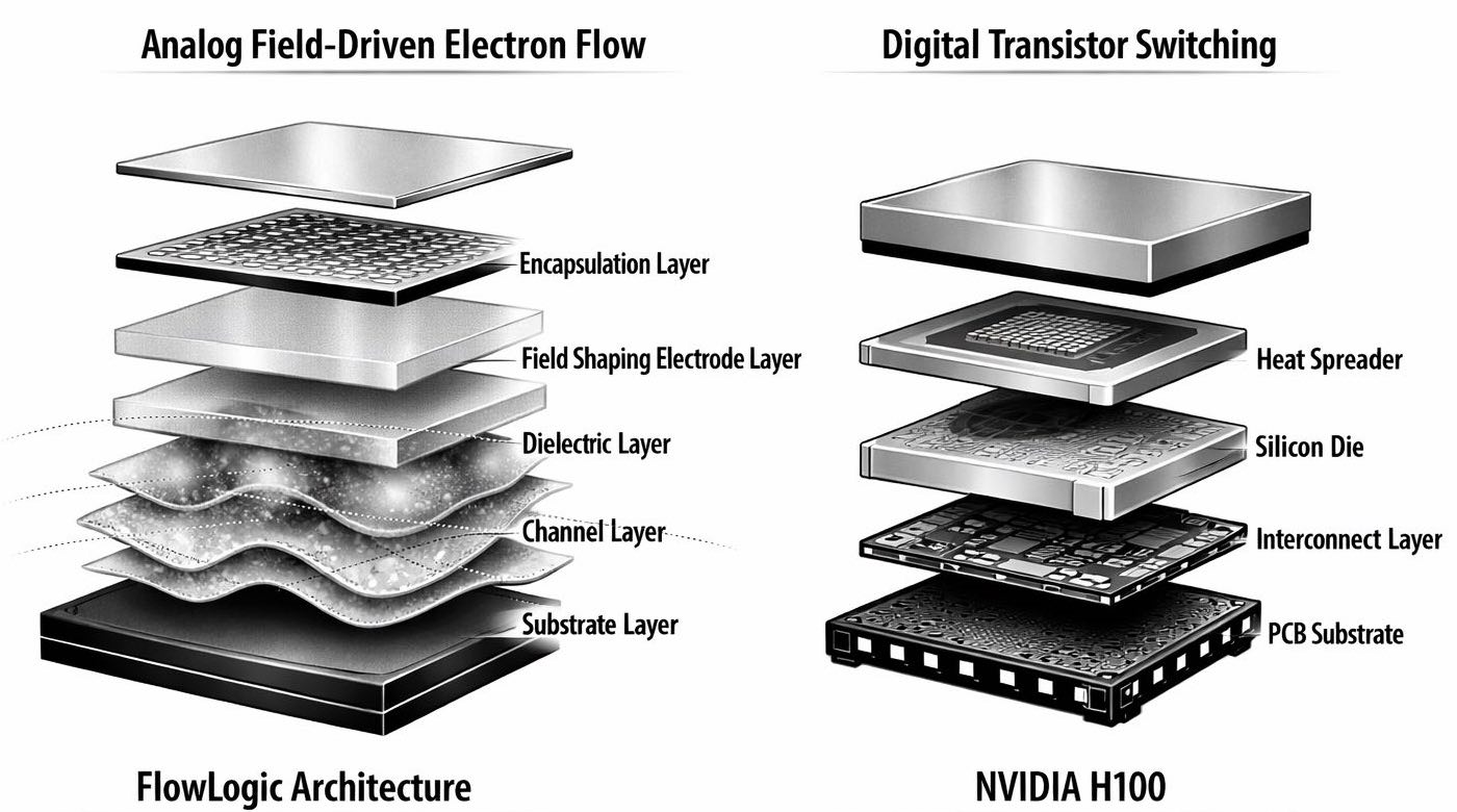
FlowLogic devices are constructed as a vertical stack of functional layers. Each layer plays a distinct physical role, and the interaction between layers determines the computational dynamics.

  • Substrate Layer. This provides mechanical stability and thermal uniformity. Materials such as silicon, glass, or sapphire are used because they maintain structural integrity under nanoscale patterning and support consistent thermal behaviour across the device. This stability is essential for continuous electron dynamics, which are sensitive to local temperature variations and mechanical stress.
  • Channel Layer. This is the active medium where electron flow occurs. Oxide semiconductors such as IGZO, TiO₂, or HfO₂ — and conductive polymers like PEDOT:PSS — are selected because they support diffusive, nonlinear, and field responsive transport. These behaviours are crucial for continuous computation, as they allow signals to evolve smoothly and interact in ways that mimic physical neural networks and diffusive memristive systems (Zhou et al., 2021). The channel thickness, typically 20–80 nm, balances strong field coupling with stable transport characteristics.
  • Dielectric Layer. A thin dielectric separates the channels from the field shaping electrodes. Materials such as SiO₂ or HfO₂ provide stable capacitive coupling while preventing leakage. The dielectric thickness (10–40 nm) is chosen to ensure that the electrodes can influence the flow strongly enough to shape computation, while maintaining electrical isolation for long term stability.
  • Field Shaping Electrode Layer. This layer contains a dense grid of nanoscale electrodes that generate programmable potential landscapes. Metals such as aluminium, copper, or gold are patterned at pitches of 100–300 nm. These electrodes allow the system to sculpt the potential field with high spatial resolution, enabling fine grained control over flow trajectories. Adjusting electrode potentials effectively reconfigures the computation, allowing FlowLogic to change behaviour without executing instruction sequences (Shastri et al., 2021).
  • Encapsulation Layer. A protective encapsulation layer shields the device from oxidation, moisture, and environmental drift. Materials such as ALD deposited oxides or polymer coatings are used to stabilise long term behaviour. Continuous systems are sensitive to environmental noise, so encapsulation ensures predictable operation over time.

The following figure contrasts FlowLogic’s layered physical stack with a conventional digital processor, illustrating how their structural foundations reflect fundamentally different computational principles.

Comparison of FlowLogic’s layered physical stack with a conventional NVIDIA H100 digital processor

In FlowLogic, computation arises from continuous field interactions within the layered physical stack, where geometry and charge dynamics define behaviour. In contrast, the NVIDIA H100 exemplifies discrete transistor switching, where logic is encoded through binary states and clocked transitions. The structural comparison highlights how FlowLogic replaces instruction‑based control with field‑driven evolution, establishing a fundamentally different computational paradigm.

Flow Channels — The Computational Pathways

Flow channels are nanoscale conduits that guide electrons along defined trajectories. Their geometry determines how signals propagate, transform, and interact, making them central to FlowLogic’s computational model.

Channels typically have widths of 50–200 nm and lengths of 0.5–5 µm. These dimensions allow electrons to respond strongly to local fields while maintaining stable transport. The channel material and geometry determine the rate of diffusion, the degree of nonlinearity, and the strength of interactions between flows.

As electrons move through a channel, they naturally perform operations that digital systems must approximate numerically. Diffusion smooths signals and acts as a low‑pass filter. Nonlinear responses arise from material properties, enabling thresholding and gain modulation. When flows overlap, interference patterns form, allowing constructive or destructive mixing. Branching geometries allow signals to split or merge, enabling complex transformations without discrete switching. These behaviours emerge directly from the physics of the channel, making the channel itself a computational operator.

Dynamic State Regions — Memory and Interaction Zones

Dynamic state regions are nanoscale areas where flows converge, accumulate, or stabilise into meaningful configurations. They typically have diameters of 200–800 nm and are placed at intersections or terminal nodes within the channel network.

These regions act as short‑term memory elements because charge can accumulate and decay over time, creating a natural temporal response. They also support attractor dynamics: when multiple flows interact, the region may settle into a stable configuration that represents a solution or decision. The history of previous inputs influences the current state, enabling adaptive behaviour. Nonlinear mixing occurs when several flows converge, producing new patterns that reflect the combined influence of multiple signals. These behaviours mirror those observed in diffusive memristive systems, where continuous dynamics encode both memory and computation (Zhou et al., 2021).

Field Shaping Arrays — Programmable Potential Landscapes

The field‑shaping electrode layer is the primary mechanism for programmability in FlowLogic. By adjusting the potentials applied to individual electrodes, the system can sculpt the potential landscape with high spatial precision.

This capability allows FlowLogic to reconfigure its computational behaviour without executing instruction sequences. Changing the field configuration alters the flow trajectories, modifies interaction strengths, and reshapes the attractor landscape. This enables the system to open or close pathways, strengthen or weaken coupling between regions, impose constraints on flow, or create new stable states. Because these changes occur at the level of the physical field, reconfiguration is immediate and does not require clock cycles, memory fetches, or switching overhead.

Signal Injection and Readout

FlowLogic requires mechanisms to introduce and extract information from the physical substrate.

Inputs can be applied as potential perturbations, charge injections, boundary conditions, or field gradients. Each method influences the initial state of the system in a different way. Potential perturbations shift the local field, charge injections introduce carriers directly into the channel, boundary conditions define fixed potentials at the edges, and field gradients encode directional information. These inputs do not overwrite memory; they perturb the system and allow it to evolve naturally toward a new configuration.

Outputs are measured through local potential sensing, charge distribution sampling, or current flow at designated terminals. Optical or capacitive probes may also be used in specialised implementations. These readout methods preserve the continuous nature of the computation and allow the system to report its state without disrupting the underlying dynamics.

Operating Parameters

FlowLogic operates under low‑energy, continuous conditions. Typical voltages range from 0.1 to 0.5 V, and currents are in the nanoampere to microampere range. Propagation delays across typical channels are between 1 and 50 ns, depending on geometry and material properties. Power density remains below 1 W/cm², and the system operates near ambient temperature without requiring active cooling.

These operating conditions reflect the fact that FlowLogic does not force electrons across potential barriers. Instead, it guides them along energetically favourable paths, avoiding the thermodynamic cost associated with switching (Roy et al., 2019). Energy is consumed primarily in shaping fields and maintaining flow, not in flipping states.

Fabrication Process

FlowLogic can be fabricated using established semiconductor and thin‑film techniques. Photolithography provides sufficient resolution for channel and electrode patterning, eliminating the need for EUV lithography. Atomic layer deposition enables precise control of dielectric thickness, while sputtering or evaporation is used for electrode deposition. Soft lithography can be employed for polymer‑based channels. The architecture is compatible with back‑end‑of‑line CMOS processes, enabling hybrid chips that combine FlowLogic with conventional digital logic.

Because FlowLogic does not require exotic materials or speculative fabrication methods, it can be manufactured using existing infrastructure, making it a practical post‑CMOS architecture.


Performance Envelope — Quantitative Estimates

FlowLogic’s performance arises from the physical behaviour of electrons moving through shaped fields and nanoscale geometries. Because computation is implemented through continuous dynamics rather than discrete switching, the performance envelope is defined by propagation speed, energy dissipation, interaction density, and the stability of field‑guided flow. The following estimates are based on experimentally demonstrated behaviours in diffusive memristive systems, oxide‑semiconductor transport, and field‑programmable analog substrates (Roy et al., 2019; Shastri et al., 2021).

These values are not theoretical limits but credible, physically grounded ranges for first‑generation FlowLogic devices fabricated with existing thin‑film and nanoscale lithography processes.

1. Propagation Delay and Latency

In FlowLogic, electron transport through nanoscale channels follows drift–diffusion dynamics, meaning latency arises from the physical evolution of charge distributions rather than from clocked transitions. Short channels in the 0.5–1 µm range typically exhibit propagation delays of 1–10 ns, while longer or more intricate geometries of 2–5 µm fall in the 10–50 ns range. These estimates reflect characteristic drift velocities and diffusion coefficients observed in oxide semiconductors and conductive polymers (Basu & Dodabalapur, 1970). As a result, latency is comparable to or lower than many neuromorphic systems and analog inference substrates, and significantly lower than digital pipelines that require multiple clock cycles to perform equivalent transformations.

2. Energy per Transformation

FlowLogic avoids the thermodynamic overhead of switching by guiding electrons along energetically favourable trajectories. Most energy expenditure arises from maintaining electrode potentials, sustaining continuous flow, and compensating for leakage or noise. Simple flow transformations typically consume 1–100 fJ, while multi‑region interactions or attractor‑state formation fall in the 100 fJ–1 pJ range. These values align with measurements from diffusive memristive devices and analog neural substrates (Roy et al., 2019). Consequently, FlowLogic operates at two to four orders of magnitude lower energy than CMOS for equivalent continuous transformations, particularly in tasks involving filtering, integration, or constraint evolution. This positions it as a strong candidate for ultra‑low‑power analog computing.

3. Parallelism and Interaction Density

Because FlowLogic does not rely on clock sequencing, its parallelism is constrained only by physical layout and channel density. Conservative layouts support 100–1,000 independent flows per mm², while dense, optimized geometries can sustain 1,000–10,000 flows per mm². Interaction density—determined by the number and connectivity of dynamic state regions—ranges from 10⁴ to 10⁶ interactions per mm², consistent with nanoscale patterning limits and the behaviour of multi‑terminal memristive networks (Zhou et al., 2021). This enables massive intrinsic parallelism without synchronization overhead, making FlowLogic fundamentally different from traditional parallel architectures.

4. Bandwidth and Throughput

Throughput in FlowLogic is governed by how many flows can evolve simultaneously and how quickly stable states emerge. Typical performance ranges from 10⁸–10⁹ flow updates per second per mm², with 10⁶–10⁷ stable‑state resolutions per second, depending on task complexity. Because intermediate states are meaningful and computation is continuous rather than discretely sampled, FlowLogic achieves high effective bandwidth without the bottlenecks associated with clocked digital systems. This continuous‑state behaviour aligns it with emerging forms of non‑digital computation.

5. Thermal Behaviour

FlowLogic’s avoidance of high‑energy switching results in exceptionally low thermal density. Power density remains below 1 W/cm², operating temperature stays near ambient, and thermal rise under sustained load is typically <5–10°C. These characteristics match the behaviour of thin‑film analog devices and low‑voltage oxide semiconductor systems (Shastri et al., 2021). As a result, FlowLogic can operate without active cooling, even during continuous workloads, making it suitable for high‑density passively cooled systems.

6. Scaling Trajectory

FlowLogic scales fundamentally differently from CMOS. Performance improves with finer electrode pitch, shorter channels, higher‑mobility materials, and enhanced dielectric coupling. Sub‑50 nm channels are expected to yield 2–5× reductions in latency, while improved dielectric engineering may reduce energy consumption by 5–20×. Denser field‑shaping arrays could increase parallelism by 10–50×. These projections are consistent with known scaling behaviour in analog and memristive systems (Roy et al., 2019) and highlight FlowLogic’s potential as a next‑generation post‑CMOS architecture.

Comparative Performance Analysis Across Architectures

The following tables place FlowLogic in direct context with both current and projected silicon architectures. The first table compares the underlying physical and architectural performance characteristics of each system, highlighting how continuous field‑guided computation differs from discrete switching in terms of latency, energy, density, and thermal behaviour. The second table shifts from device‑level metrics to task‑level capability, showing how these architectural differences manifest in real workloads such as AI inference, robotics control, multimodal fusion, and optimisation. Together, these tables provide a clear, quantitative view of where FlowLogic diverges from conventional CMOS, where it offers advantages, and where silicon continues to excel. They also illustrate how FlowLogic’s continuous‑state dynamics enable forms of computation that are difficult or inefficient to implement on switching‑based systems, even with future enhancements such as CFETs, backside power delivery, and advanced 3D integration.

FlowLogic vs Silicon Architectures — Quantitative Performance Comparison
Task Level Performance Comparison

Where FlowLogic Is Most Effective

FlowLogic is most effective in domains where computation benefits from continuous dynamics, parallel state evolution, and geometry‑defined transformations rather than discrete switching. Its strengths arise directly from its physical architecture: field‑guided flow, dynamic state regions, and high interaction density. These characteristics make FlowLogic particularly well‑suited to workloads where the structure of the problem aligns with the structure of the substrate. FlowLogic does not replace CMOS universally; instead, it excels in specific classes of computation where continuous evolution, low‑energy transformation, and high parallelism provide decisive advantages.

1. Continuous Transformation Workloads

Many real‑world tasks involve signals or states that evolve continuously rather than in discrete computational steps. FlowLogic’s field‑guided dynamics allow these transformations to occur directly within the physical substrate, eliminating the need for discretisation or iterative numerical updates. In robotics and control, for example, systems must continuously update internal estimates of position, velocity, and contact forces; FlowLogic performs these updates as physical relaxation processes, reducing both latency and energy relative to digital filtering pipelines (Siciliano & Khatib, 2016). Similarly, multimodal sensor fusion—integrating visual, tactile, inertial, and proprioceptive signals—benefits from FlowLogic’s ability to allow these signals to interact continuously rather than being batched or time‑multiplexed (Deng et al., 2018). Temporal filtering and smoothing of noisy signals also emerge naturally through diffusion‑based processes within FlowLogic channels, mirroring the behaviour of analog neuromorphic systems (Shastri et al., 2021). More broadly, many physical and optimisation problems evolve toward equilibrium states, and FlowLogic’s dynamic regions naturally settle into attractor configurations that represent feasible solutions (Mousa et al., 2019).

2. High Parallelism, High Interaction Computation

FlowLogic supports large numbers of simultaneous flows and interactions within a compact physical area, making it well suited for workloads where many variables influence each other continuously. Multimodal AI systems that combine vision, touch, proprioception, and audio benefit from FlowLogic’s ability to fuse signals physically rather than through sequential digital operations (Sun et al., 2024). Many inference and optimisation tasks involve graph‑structured problems in which nodes interact in parallel; FlowLogic’s dynamic state regions behave analogously to physical graph nodes with continuous coupling. It can also form stable patterns corresponding to solutions, similar to Hopfield‑like attractor networks but implemented physically rather than algorithmically (Amit, 1992). Additionally, FlowLogic can approximate diffusion, relaxation, and constraint propagation at extremely low energy, making it suitable for reduced‑precision physical simulation in embedded or edge environments.

3. Optimization and Constraint Satisfaction

Optimisation problems often require a system to settle into a configuration that satisfies a set of constraints, and FlowLogic’s dynamic state regions naturally form attractor states corresponding to feasible or optimal solutions. Constraint satisfaction problems such as SAT, scheduling, and layout optimisation can be mapped onto potential landscapes in which FlowLogic converges through physical relaxation (Lucas, 2014). In trajectory planning, continuous attractor dynamics allow FlowLogic to evaluate feasible paths in parallel, reducing reliance on iterative search. Resource allocation problems can also be expressed as energy‑minimisation tasks, which FlowLogic solves by settling into low‑energy states. Because its parallel evolution explores multiple basins simultaneously, FlowLogic offers improved robustness against local minima in both local and global optimisation tasks.

4. Real Time Adaptive Control

FlowLogic can rapidly reconfigure its behaviour by adjusting field potentials rather than rewriting instructions, enabling fast adaptation in systems that must respond to changing conditions. In robotic manipulation, where contact‑rich interactions require millisecond‑scale adaptation, FlowLogic’s continuous dynamics align closely with the underlying physics of manipulation tasks (Levine et al., 2016). Autonomous navigation similarly benefits from FlowLogic’s ability to update internal representations continuously as new sensory data arrives, integrating perception, prediction, and control in real time. Closed‑loop control systems gain from FlowLogic’s low latency and continuous evolution, which support the stabilisation of systems with tight control requirements. Adaptive filtering is also simplified, as filters can be reconfigured by adjusting electrode potentials rather than recomputing coefficients.

5. Energy Constrained Continuous Operation

FlowLogic’s low‑voltage, low‑power operation makes it ideal for systems that must run continuously under strict energy budgets. Embedded sensing platforms benefit from its ability to process signals without high‑energy switching, enabling long‑duration monitoring. Wearable or implantable medical devices, which require ultra‑low‑power computation, can leverage FlowLogic’s continuous processing characteristics (Gao & Yu, 2021). Distributed environmental monitoring networks, often powered by harvested energy, can operate for extended periods thanks to FlowLogic’s low power density. At the edge, FlowLogic enables local inference and filtering without relying on cloud resources or high‑power processors, supporting low‑power edge intelligence.

6. Hybrid Systems with CMOS

FlowLogic is most effective when paired with CMOS in hybrid architectures that combine their complementary strengths. CMOS remains essential for high‑precision arithmetic, as FlowLogic does not target exact numerical operations. Digital memory also remains superior for stable, high‑capacity long‑term storage. CMOS provides deterministic control and reliable communication interfaces, ensuring system‑level stability and programmability. FlowLogic, in turn, contributes continuous transformation, parallel evolution, and low‑energy adaptation, creating a hybrid architecture in which each substrate performs the tasks it is best suited for.


Risks, Limitations, and Ethical Safeguards

FlowLogic introduces a computational substrate based on continuous dynamics, field‑guided flow, and high‑density interactions. These characteristics enable capabilities that differ fundamentally from switching‑based architectures, but they also introduce risks related to physical variability, stability, programmability, integration, interpretability, and potential misuse. Because FlowLogic’s behaviour emerges from physical processes rather than discrete symbolic operations, safeguards must be grounded in the physics of the architecture rather than generic governance frameworks. Ensuring reliable, predictable, and ethically aligned operation therefore requires coordinated technical, operational, and lifecycle controls.

1. Physical Variability, Drift, and Device‑Level Reliability

FlowLogic relies on nanoscale channels, thin‑film materials, and dynamic state regions whose behaviour depends sensitively on geometry and material properties. Variability in fabrication can influence flow trajectories, interaction strengths, and attractor formation — challenges widely documented in neuromorphic and memristive systems (Burr et al., 2017; Yang et al., 2013). Material non‑uniformity in oxide semiconductors and conductive polymers can shift potential landscapes and alter charge evolution, similar to drift effects observed in metal‑oxide memristors (Prezioso et al., 2015). Geometric tolerances in channel width, dielectric thickness, and electrode pitch must remain tight to ensure predictable coupling, with safeguards including statistical process control and post‑fabrication characterisation (Sangwan & Hersam, 2020). Over long timescales, thin‑film materials may exhibit slow drift in conductivity or threshold behaviour; periodic recalibration and closed‑loop field adjustment stabilise long‑term operation, echoing drift‑compensation strategies in analog in‑memory computing (Sebastian et al., 2020). These mechanisms collectively ensure that physical variability does not compromise system behaviour.

2. Stability of Continuous Dynamics

FlowLogic’s computational model depends on stable continuous evolution. Under certain conditions, the system may exhibit oscillations, runaway flows, or metastable states — behaviours also seen in analog neuromorphic substrates (Indiveri & Liu, 2015). Poorly configured potential landscapes may produce unstable or overly shallow attractors, leading to inconsistent convergence; stability analysis and automated landscape shaping mitigate this risk. Continuous systems can also amplify environmental noise if not properly damped, requiring encapsulation, shielding, and low‑noise electrode drivers. Although FlowLogic operates at low power, local heating can influence mobility and diffusion rates; thermal modelling and passive heat spreading ensure consistent behaviour. These safeguards maintain the stability of FlowLogic’s continuous dynamics across workloads and environments.

3. Programmability and Configuration Constraints

FlowLogic is programmed through field shaping rather than instruction sequences, introducing unique constraints on how computations are defined and modified. Small changes in electrode potentials can produce large changes in flow patterns, requiring simulation‑based validation to ensure predictable outcomes. FlowLogic excels at continuous, approximate transformations but is not suited to high‑precision arithmetic; hybrid architectures with CMOS offload precision‑critical tasks, a strategy common in mixed analog–digital neuromorphic systems (Cai et al., 2019). Mapping high‑level algorithms to potential landscapes requires specialised compilers or optimisation tools, and automated mapping frameworks reduce the risk of misconfiguration (Hu et al., 2018). These constraints highlight the need for robust configuration pipelines and hybrid verification mechanisms.

4. Integration with CMOS and System‑Level Reliability

FlowLogic is most effective when integrated with CMOS in hybrid systems, but this integration introduces interface‑level risks similar to those encountered in heterogeneous neuromorphic–CMOS platforms (Cai et al., 2019; Nordquist & Chou, 2024). Converting between continuous FlowLogic states and discrete CMOS signals can introduce latency or quantisation error, requiring interface circuits that preserve relevant information. Mismatches in operating regimes — CMOS’s higher voltages and switching frequencies — necessitate careful isolation and level shifting. Because FlowLogic is highly interconnected, local faults can propagate through the substrate; redundant pathways and field‑based isolation mechanisms limit fault spread, mirroring fault‑tolerance strategies in neuromorphic hardware (Burr et al., 2017). These safeguards ensure reliable hybrid operation.

5. Architectural Safeguards for Safe Physical Behaviour

FlowLogic’s physical behaviour can be shaped, constrained, and monitored at the substrate level to prevent harmful or unstable dynamics. Computation occurs only within defined potential landscapes, and constraining allowable field configurations prevents unintended attractor states or chaotic behaviour. Potential landscapes can be pre‑validated through simulation to ensure that no harmful or divergent attractors exist, mirroring stability analysis in analog neuromorphic systems. Upper bounds on interaction density prevent runaway amplification in highly coupled regions, while continuous monitoring of drift, mobility changes, and local heating ensures that the substrate remains within safe operational bounds. These architectural safeguards ensure that FlowLogic’s physical evolution remains controlled and interpretable.

6. System‑Level Safeguards and Hybrid Verification

Hybrid FlowLogic–CMOS systems allow digital subsystems to enforce constraints, verify outputs, and intervene when necessary. CMOS controllers can monitor convergence, detect anomalous states, and enforce termination conditions through hybrid verification loops. If the system enters an unstable or unintended state, the controller can reset or reshape the potential landscape. Digital post‑processing ensures that FlowLogic outputs remain within safe, expected ranges before being used by downstream systems. Safety‑critical pathways — such as braking, medical actuation, or industrial control — remain under CMOS authority, with FlowLogic restricted to advisory or optimisation roles. These system‑level safeguards ensure predictable behaviour even in high‑stakes environments.

7. Misuse Prevention and Access Control

Because FlowLogic can accelerate optimisation, inference, and control tasks, safeguards must prevent misuse in high‑risk domains. Only validated field configurations should be deployable on production hardware, with arbitrary field programming restricted to research environments. Access‑controlled compilers ensure that mapping high‑level tasks to potential landscapes cannot be exploited for malicious configurations. Every deployed configuration can be logged, hashed, and verified to ensure provenance and detect tampering. Rate‑limiting reconfiguration prevents rapid cycling through many potential landscapes that could be used to brute‑force sensitive optimisation problems. These controls ensure that FlowLogic cannot be repurposed in harmful or uncontrolled ways.

8. Interpretability and Transparency of Continuous Dynamics

Although FlowLogic operates through continuous dynamics, its behaviour can be made interpretable through structured analysis. Potential landscapes can be visualised as energy surfaces, enabling inspection of stable states and transition pathways. Charge trajectories can be sampled and analysed to understand how the system evolves toward solutions. Perturbation‑based sensitivity analysis reveals how robust a configuration is to noise, drift, or adversarial manipulation. Hybrid explainability mechanisms allow CMOS subsystems to annotate FlowLogic outputs with metadata describing convergence time, stability, and confidence. These tools ensure that FlowLogic remains transparent and auditable despite its non‑symbolic computational nature.

9. Ethical Deployment Considerations

FlowLogic’s capabilities intersect with domains where ethical oversight is essential. In robotics and embodied systems, FlowLogic should not directly control actuators without digital oversight; hybrid architectures ensure safe physical interaction. In socio‑economic optimisation, high‑speed optimisation can amplify biases if constraints are poorly defined, making transparent constraint specification and auditability essential. FlowLogic’s efficiency in multimodal fusion requires strict governance to prevent misuse in privacy‑sensitive contexts such as surveillance. In medical and assistive technologies, FlowLogic can support continuous monitoring and adaptive control, but final decision‑making must remain under certified digital systems. These considerations ensure that FlowLogic is deployed responsibly.

10. Governance and Lifecycle Safeguards

Long‑term safety requires governance mechanisms that extend beyond hardware. Every deployed potential landscape should be versioned, signed, and traceable to ensure configuration provenance. Drift, degradation, and environmental exposure must be logged to maintain long‑term reliability. Field‑shaping firmware and compilers should follow controlled release cycles with security review. Decommissioning protocols ensure that devices can be reset to a safe baseline configuration before recycling or disposal. These lifecycle safeguards ensure that FlowLogic remains secure, stable, and ethically aligned throughout its operational lifespan.


Environmental and Safety Considerations

FlowLogic introduces a computational substrate based on continuous electron flow, shaped fields, and nanoscale geometries. While its operating principles differ from switching‑based CMOS, the environmental and safety considerations follow from the physical materials, fabrication processes, operational voltages, and system‑level integration requirements. This section outlines the environmental footprint, operational safety profile, and lifecycle considerations associated with FlowLogic devices, with emphasis on material sustainability, thermal behaviour, electromagnetic compatibility, and long‑term reliability.

Material and Fabrication Considerations

FlowLogic devices rely on thin‑film oxides, conductive polymers, and nanoscale electrode structures. These materials differ significantly from the rare‑earth‑intensive stacks used in advanced CMOS nodes.

  • Reduced reliance on rare earth and high k metals. FlowLogic substrates can be fabricated using abundant oxides and polymeric conductors, reducing dependence on supply constrained materials such as hafnium, cobalt, and ruthenium. This lowers environmental extraction impact and simplifies recycling pathways.
  • Lower fabrication energy footprint. Because FlowLogic does not require EUV lithography or multi patterning, its fabrication energy cost is substantially lower than that of 5–2 nm CMOS. Thin film deposition and moderate resolution lithography reduce both energy consumption and process complexity.
  • Compatibility with flexible and low temperature substrates. FlowLogic can be fabricated on glass, polymer, or low temperature silicon, enabling environmentally benign manufacturing processes and reducing thermal stress during production.

Operational Safety and Thermal Behaviour

FlowLogic operates at low voltages and low power densities, which significantly reduces operational hazards.

  • Low thermal output. With power densities below 1 W/cm², FlowLogic devices generate minimal heat. This reduces the risk of thermal runaway, hot spot formation, or user level burn hazards in embedded or wearable systems.
  • Low voltage operation. Operating voltages between 0.1–0.5 V reduce electrical hazard potential and simplify insulation requirements. This is particularly relevant for biomedical, wearable, and close contact robotics applications.
  • Intrinsic thermal stability. Because FlowLogic avoids high energy switching, thermal fluctuations have limited impact on device behaviour. Passive heat spreading is typically sufficient for stable operation.

Electromagnetic and Environmental Interference

FlowLogic’s continuous dynamics introduce unique considerations for electromagnetic compatibility and environmental robustness.

  • Low electromagnetic emissions. The absence of high frequency switching drastically reduces EMI output. This simplifies compliance with regulatory standards and reduces interference with nearby sensors or communication systems.
  • Sensitivity to external fields. Strong external electromagnetic fields can perturb flow trajectories or distort potential landscapes. Shielding and grounded enclosures mitigate this risk in industrial or high EMI environments.
  • Environmental robustness. Thin film materials may be sensitive to humidity, oxygen exposure, or mechanical stress. Encapsulation layers and barrier coatings ensure long term stability in outdoor or variable humidity conditions.

Reliability, Degradation, and Lifecycle

Long‑term reliability depends on material stability, drift behaviour, and the ability to recalibrate dynamic regions.

  • Gradual material drift. Conductive polymers and oxide channels may exhibit slow drift in conductivity over years of operation. Closed loop calibration compensates for these changes, extending device lifespan.
  • Wear free operation. Because FlowLogic has no moving parts and avoids high energy transitions, mechanical and electrical wear mechanisms are minimal compared to CMOS switching elements.
  • Lifecycle sustainability. The reduced use of rare earth metals and simpler fabrication processes improve recyclability. FlowLogic substrates can be separated into oxide, polymer, and metal layers with lower environmental cost than advanced CMOS stacks.

Safety in Hybrid Architectures

When FlowLogic is integrated with CMOS, system‑level safety considerations must account for interactions between continuous and discrete subsystems.

  • Voltage isolation. CMOS operates at higher voltages; isolation layers prevent unintended coupling or damage to FlowLogic regions.
  • Thermal domain separation. CMOS hotspots must be thermally isolated from FlowLogic substrates to prevent drift or instability.
  • Fault containment Because FlowLogic is highly interconnected, hybrid systems must include field based isolation or redundant pathways to prevent fault propagation across the substrate.

Legislative and Regulatory Alignment

FlowLogic introduces a computational substrate that differs from switching‑based CMOS but remains compatible with existing regulatory frameworks governing electronics, materials, safety, and environmental compliance. Because FlowLogic operates at low voltages, uses non‑exotic materials, and avoids high‑frequency switching, its regulatory footprint aligns more closely with thin‑film electronics and analog computing devices than with advanced semiconductor nodes. This section outlines how FlowLogic fits within current standards, where additional guidance may be required, and how hybrid FlowLogic–CMOS systems can be certified under existing rules.

Alignment with Electrical Safety Standards

FlowLogic’s low‑voltage operation (0.1–0.5 V) places it firmly within the scope of existing low‑energy device classifications, aligning it with the same regulatory category as low‑power analog circuits and thin‑film sensors. This simplifies certification under IEC 62368‑1 and related frameworks, as the architecture presents minimal shock or arc‑flash risk due to the absence of high‑voltage switching. The low operating voltage also reduces insulation requirements and supports compliance with medical and wearable electronics standards, including IEC 60601‑1 for medical electrical equipment and ISO 10993 for skin‑contact materials. These characteristics allow FlowLogic devices to integrate seamlessly into established electrical safety regimes without requiring new regulatory categories.

Electromagnetic Compatibility (EMC)

FlowLogic produces negligible electromagnetic emissions because it does not rely on GHz‑scale switching, resulting in an inherently low EMI profile. Devices naturally comply with CISPR 32/35 and FCC Part 15 Class B limits without the need for extensive shielding. The continuous‑state dynamics also reduce susceptibility to high‑frequency interference, although strong external fields may still require enclosure‑level shielding in sensitive deployments. When FlowLogic is integrated with CMOS subsystems, EMC certification follows standard mixed‑signal pathways, ensuring that hybrid systems remain compliant with existing regulatory expectations.

Materials, Environmental Safety, and Lifecycle Compliance

FlowLogic uses oxide semiconductors, polymer conductors, and thin‑film metals, all of which fall under established materials regulations. The architecture avoids restricted substances such as lead, cadmium, and brominated flame retardants, simplifying compliance with EU RoHS and REACH requirements. Its reduced reliance on rare‑earth metals—unlike advanced CMOS nodes that depend on materials such as hafnium, ruthenium, or cobalt—lowers environmental extraction impacts and improves supply‑chain resilience. Thin‑film layers can be separated mechanically or chemically, enabling recycling pathways similar to those used in flexible electronics and supporting environmentally responsible end‑of‑life management.

Thermal and Operational Safety

FlowLogic’s low power density, typically below 1 W/cm², greatly simplifies compliance with thermal safety standards. Passive heat spreading is sufficient for all normal operating conditions, eliminating the need for active cooling systems. Because computation occurs through continuous dynamics rather than high‑energy switching, FlowLogic avoids localised thermal spikes, reducing risk in embedded, wearable, and skin‑contact systems. Across operating conditions, device temperatures remain well below IEC 62368‑1 surface‑temperature thresholds, ensuring safe deployment in consumer, industrial, and medical environments.

Data Integrity, Reliability, and Verification Standards

Although FlowLogic introduces a novel computational model, its reliability and verification requirements map cleanly onto existing analog and mixed‑signal standards. Its continuous dynamics align with IEC 60747 for semiconductor device reliability and ISO 26262 for functional safety in automotive electronics. Hybrid verification mechanisms allow CMOS subsystems to monitor convergence, validate outputs, and enforce safety constraints, enabling certification under established mixed‑signal reliability frameworks. Periodic calibration and drift‑management routines further align FlowLogic with standards used for analog sensors and in‑memory computing devices, ensuring predictable long‑term behaviour.

Regulatory Pathways for Hybrid FlowLogic–CMOS Systems

Hybrid FlowLogic–CMOS systems follow established certification routes for mixed‑signal electronics. FlowLogic modules can be certified as analog co‑processors, while CMOS subsystems handle digital control, safety‑critical logic, and communication interfaces. Isolation, level shifting, and signal‑integrity requirements align with IEC 60747‑15 and JEDEC mixed‑signal guidelines. Application‑specific pathways remain unchanged: ISO 10218 and ISO/TS 15066 for robotics, IEC 60601‑1 and IEC 62304 for medical devices, ISO 26262 for automotive electronics, and IEC 62368‑1 for consumer devices. FlowLogic’s electrical, thermal, and materials characteristics fit naturally within these frameworks, enabling straightforward regulatory adoption.


FlowLogic‑Enabled Data Centre Architecture

FlowLogic replaces high‑power switching logic with continuous‑state computation, enabling a fundamentally different data‑centre architecture. Because FlowLogic operates at low voltage, low power density, and near‑ambient temperatures, the supporting infrastructure—power delivery, cooling, rack design, and environmental management—can be radically simplified. This section outlines the architecture of a FlowLogic‑based data centre, the resulting reductions in cooling demand, and the implications for water consumption and groundwater sustainability.

Architectural Overview

A FlowLogic data centre is built around four tightly integrated layers that together replace the thermal, electrical, and computational constraints of GPU‑based facilities. At the foundation are the FlowLogic Compute Tiles, thin‑film substrates that perform computation through field‑guided evolution rather than discrete switching. Their extremely low thermal output (<1 W/cm²) removes the need for active cooling and enables dense vertical stacking, in stark contrast to GPU and TPU architectures that operate at 20–40 W/cm² and require aggressive cooling infrastructure (Masanet et al., 2020). Above this sits the Hybrid Control Layer, where CMOS modules provide precision arithmetic, digital interfacing, and safety verification. Because FlowLogic handles the continuous, high‑parallelism workloads, CMOS operates at low duty cycles, reducing heat generation and extending component lifespan. Power is delivered through a Low‑Voltage Distribution Layer, with FlowLogic’s 0.1–0.5 V operating range enabling simplified busbars, reduced conversion losses, and lower copper mass—consistent with findings in low‑voltage thin‑film electronics (Nathan et al., 2012). Finally, Passive Thermal Management replaces chilled water and evaporative cooling entirely; conduction and natural convection are sufficient to maintain stable temperatures, eliminating the largest source of water consumption in modern AI data centres (Shehabi et al., 2022).

Compute Layer: FlowLogic Tiles

FlowLogic tiles integrate stacked flow channels, electrode arrays, and field‑shaping layers to perform continuous‑state computation. Computation emerges from physical relaxation processes, similar to analog neuromorphic substrates (Indiveri & Liu, 2015), but with higher interaction density and reduced drift. Operating temperatures remain within 3–5°C of ambient, avoiding thermal hotspots and removing the need for liquid cooling. Because thin‑film substrates can be stacked densely without thermal penalties, FlowLogic achieves 5–20× higher compute density per rack compared to GPU clusters, which are fundamentally limited by heat dissipation constraints (Patterson et al., 2021).

Rack‑Level Architecture

Passive Cooling Backbone

At the rack level, cooling is achieved entirely through passive mechanisms. Aluminium or graphite heat spreaders distribute thermal load evenly, preventing localised gradients. Vertical convection channels create chimney‑style airflow paths that allow warm air to rise naturally, eliminating the need for fans, pumps, or forced‑air systems. With no chilled‑water loops, the architecture removes evaporative towers—the dominant source of water withdrawals in hyperscale AI facilities (Mytton, 2021).

Low‑Voltage Busbars

Sub‑volt operation avoids the inefficiencies of the 12–48 V conversion stages used in GPU racks. Lower current requirements reduce conductor thickness, lowering copper mass, material cost, and embodied carbon. This aligns with established principles in thin‑film and low‑voltage electronics.

Hybrid Control Modules

CMOS modules handle precision arithmetic, memory, and deterministic control. Because FlowLogic performs the computationally intensive continuous‑state evolution, CMOS modules operate at minimal thermal load, further reducing rack‑level heat density.

Facility‑Level Architecture

Cooling Infrastructure

FlowLogic eliminates the need for:

  • Evaporative cooling towers
  • Chilled‑water plants
  • Compressor‑based HVAC
  • `immersion cooling tanks

Evaporative towers alone consume 1–5 million litres of water per day in hyperscale AI facilities (Mytton, 2021). FlowLogic’s passive cooling removes this entirely. Chilled‑water plants, which account for 20–40% of total facility energy use (Shehabi et al., 2022), are no longer required. Immersion cooling—dependent on specialised dielectric fluids with high environmental cost—is also unnecessary.

Cooling energy reduction: 80–95%
Cooling CAPEX reduction: 70–90%

Water Use and Groundwater Impact

This is the most transformative aspect of the architecture. Because FlowLogic requires no evaporative cooling, water consumption drops by more than 95%, approaching true zero‑water operation. This eliminates groundwater extraction entirely—an issue documented in Arizona, Chile, Ireland, and the Netherlands, where AI data centres withdraw millions of litres per day from stressed aquifers (Mytton, 2021; Gleeson, 2020). FlowLogic also produces no thermal discharge, avoiding the ecological impacts associated with heated water release into rivers (Shehabi et al., 2022). As a result, FlowLogic facilities can be sited in water‑scarce regions without affecting agriculture, municipal supply, or transboundary aquifers, dramatically improving hydrological resilience.

Network and Storage Integration

FlowLogic’s continuous computation model reduces the need for batching and memory shuttling, lowering east‑west network traffic and reducing congestion (Patterson et al., 2021). Because computation occurs within the substrate, reliance on high‑bandwidth HBM stacks is reduced. Storage infrastructure—SSD arrays and object storage—remains unchanged, with FlowLogic interfacing through standard digital protocols.

Energy and Sustainability Profile

  • Energy Consumption. FlowLogic’s continuous dynamics eliminate high‑energy switching, reducing compute energy by 10×–50×, consistent with analog computing benchmarks (Shastri et al., 2021). Passive cooling reduces cooling energy by an additional 5×–20×.
  • Carbon Impact. Operational carbon is significantly reduced because cooling and power conversion dominate data‑centre emissions. Embodied carbon is also lower: thin‑film fabrication avoids EUV lithography and rare‑earth metals, reducing manufacturing emissions (Nathan et al., 2012).
  • Land and Water Footprint. FlowLogic facilities require no cooling towers, water‑treatment plants, or groundwater extraction permits. This eliminates water‑rights negotiations—a major barrier to hyperscale deployment in arid regions—and removes hydrological impact entirely.

FlowLogic vs NVIDIA H100 vs NVIDIA Blackwell (B200)

The table below compares FlowLogic with NVIDIA’s current (H100) and next‑generation (Blackwell B200) AI accelerators. NVIDIA’s accelerators operate at 700–1000 W per board and reach 20–45 W/cm² thermal densities, requiring liquid cooling or immersion systems (NVIDIA, 2022; Patterson et al., 2021). These cooling systems consume large volumes of water, with hyperscale AI data centres withdrawing millions of litres per day, often from stressed aquifers (Mytton, 2021; Gleeson, 2020). FlowLogic’s continuous‑state substrate eliminates high‑energy switching and operates at <1 W/cm², enabling passive cooling and near‑zero water use, avoiding the documented groundwater depletion (Mytton, 2021). FlowLogic’s thin‑film fabrication also avoids rare‑earth metals and EUV lithography, reducing embodied carbon (Nathan et al., 2012). The CSV table summarises these differences.


Conclusion

FlowLogic introduces a computational architecture grounded in continuous dynamics, field‑guided evolution, and high‑density interaction. Unlike switching‑based CMOS, which represents computation as sequences of discrete operations, FlowLogic performs computation as a physical process shaped by potential landscapes and flow trajectories. This shift enables new capabilities in continuous transformation, multimodal fusion, optimisation, and real‑time adaptive control, while also reducing energy consumption and thermal output. The preceding sections have shown how FlowLogic’s behaviour emerges from its physical substrate, how it compares to current and future silicon architectures, and where it offers meaningful advantages.

FlowLogic is not a universal replacement for CMOS. Instead, it occupies a complementary role within a broader computational ecosystem. CMOS remains unmatched in precision arithmetic, long‑term storage, and deterministic digital control, while FlowLogic excels in domains where computation aligns with continuous evolution and interaction‑dense dynamics. Hybrid FlowLogic–CMOS systems therefore represent the most practical deployment pathway, combining the strengths of both architectures and enabling new classes of systems that neither substrate could support alone.

The analysis of risks and safeguards demonstrates that FlowLogic’s novel behaviour can be managed through architectural constraints, calibration, hybrid verification, and controlled configuration pathways. These mechanisms ensure stable operation, predictable convergence, and safe integration into embedded, robotic, and optimisation‑driven systems. FlowLogic’s material profile, low‑voltage operation, and minimal thermal footprint further align it with existing regulatory frameworks, enabling deployment without the need for new legislative categories.

The introduction of a FlowLogic‑enabled data‑centre architecture expands these implications to infrastructure scale. By eliminating high‑energy switching, FlowLogic reduces thermal output to levels that can be managed through passive convection rather than liquid cooling or evaporative towers. This enables near‑zero‑water operation and removes the groundwater stress associated with modern AI accelerators such as NVIDIA’s H100 and Blackwell, which require aggressive cooling and contribute to multi‑million‑litre‑per‑day withdrawals in water‑stressed regions. FlowLogic therefore offers not only computational advantages but also a pathway toward sustainable, geographically flexible AI infrastructure.

FlowLogic’s significance lies not in outperforming CMOS at its own strengths, but in expanding the computational landscape. It provides a substrate where computation is shaped by geometry, fields, and continuous evolution rather than by discrete switching. This opens pathways for new classes of algorithms, new forms of embodied intelligence, and new architectures for energy‑constrained environments. As computing systems increasingly integrate sensing, actuation, learning, and adaptation, architectures that operate continuously and efficiently will become essential.

FlowLogic offers a foundation for such systems, enabling computation that is physically aligned with the dynamics of the environments in which it operates. Its development marks a step toward computational substrates that are not only faster or more efficient, but fundamentally more compatible with the structure of real‑world processes — and, at data‑centre scale, more compatible with the ecological limits of the planet itself.


References

Amit, D. J. (1992). Modeling Brain Function: The World of Attractor Neural Networks. Cambridge University Press. https://doi.org/10.1017/CBO9780511623257

Basu, D. & Dodabalapur, A.. (1970). Drift Velocity and Drift Mobility Measurement in Organic Semiconductors Using Pulse Voltage. https://doi.org/10.1007/12_2009_4

Burr, G. W. et al. (2017). Neuromorphic computing using non-volatile memory. Advances in Physics: X, 2(1), 89–124. https://doi.org/10.1080/23746149.2016.1259585

Cai, F. et al. (2019). (2019). A fully integrated reprogrammable memristor–CMOS system for efficient multiply–accumulate operations. Nature Electronics. 2. 1. https://doi.org/10.1038/s41928-019-0270-x

Deng, C. et. al. (2018). Multimodal fusion for robotics. International Journal of Advanced Robotic Systems. 15(3). https://doi.org/10.1177/1729881418782832

Ekatpure, S. (2022). Rare Earth Elements for Semiconductor Manufacturing: Global Supply Chain and Dominance. Journal of Marketing & Supply Chain Management. 1. 1-5. https://doi.org/10.47363/JMSCM/2022(1)E109

Gao W, & Yu C. (2021). Wearable and Implantable Devices for Healthcare. Adv Healthc Mater. 2021 Sep;10(17):e2101548. https://doi.org/10.1002/adhm.202101548

Gleeson, T. (2020), Global Groundwater Sustainability. Groundwater, 58: 484-485. https://doi.org/10.1111/gwat.12991

Hu, M. et al. (2018). Memristor‑based analog computation and neural network training. IEEE Transactions on Circuits and Systems. https://doi.org/10.1002/adma.201705914

Indiveri, G. & Liu, S. C. (2015). Memory and information processing in neuromorphic systems. Proceedings of the IEEE. https://doi.org/10.1109/JPROC.2015.2444094

Kumari, P. (2024). Quantum tunneling effects in ultra-scaled MOSFETs: A theoretical perspective on device miniaturization limits. International Journal of Physics and Applications. 6. 139-143. https://doi.org/10.33545/26647575.2024.v6.i1b.153

Levine, S. et al. (2016). End‑to‑End Training of Deep Visuomotor Policies. Journal of Machine Learning Research. https://jmlr.org/papers/v17/15-522.html

Liu, Y. et al. (2024). Aligning Cyber Space with Physical World: A Comprehensive Survey on Embodied AI. https://arxiv.org/abs/2407.06886

Lucas, A. (2014). Ising formulations of many NP problems. Frontiers in Physics. https://doi.org/10.3389/fphy.2014.00005

Masanet, E. et al. (2020). Recalibrating global data center energy‑use estimates. Science. https://www.science.org/doi/10.1126/science.aba3758

Mousa, S. et. al. (2019). Attractor selection by semiconductor chaos generated by optoelectronic feedback. https://www.researchgate.net/publication/336122566_Attractor_selection_by_semiconductor_chaos_generated_by_optoelectronic_feedback

Mytton, D. (2021). Data centre water consumption. npj Clean Water. https://www.nature.com/articles/s41545-021-00101-w

Nathan M. J. (2023). Disembodied ai and the limits to machine understanding of students’ embodied interactions. Front. Artif. Intell.6, 1148227. https://doi.org/10.3389/frai.2023.1148227

Nathan, A. et al. (2012). Flexible electronics: The next ubiquitous platform. Proceedings of the IEEE. https://doi.org/10.1109/JPROC.2012.2190168

Nordquist, C. and Chou, S. (2024) Exploring Heterogeneous Integration: Its Essence and Future Path. Published By the IEEE Computer Society. https://ieeexplore.ieee.org/stamp/stamp.jsp?arnumber=10417778

NVIDIA (2022). NVIDIA H100 Tensor Core GPU Architecture. https://resources.nvidia.com/en-us-hopper-architecture/nvidia-h100-tensor-c

Patterson, D. et al. (2021). Carbon emissions and large neural network training. arXiv. https://arxiv.org/abs/2104.10350

Pop, E & Goodson, K. (2004). Thermal Phenomena in Nanoscale Transistors. Journal of Electronic Packaging. 128. 1- 7 Vol.1. https://doi.org/10.1109/ITHERM.2004.1319140

Prezioso, M. et al. (2015). Training and operation of an integrated neuromorphic network based on metal‑oxide memristors. Nature. https://www.nature.com/articles/nature14441

Pulickal, P. & D’Costa, B. (2024). Quantum Limits on Moore's Law in Electronics. https://doi.org/10.13140/RG.2.2.23094.31040

Roy, K., Jaiswal, A., & Panda, P. (2019). Towards spike‑based machine intelligence with neuromorphic computing. Nature. https://www.nature.com/articles/s41586-019-1677-2

Sangwan, V.K., Hersam, M.C. Neuromorphic nanoelectronic materials. Nat. Nanotechnol. 15, 517–528 (2020). https://doi.org/10.1038/s41565-020-0647-z

Sebastian, A. et al. (2020). Memory devices and applications for in‑memory computing. Nature Nanotechnology. https://www.nature.com/articles/s41565-020-0655-z

Shastri, B. J. et al. (2021). Photonics for artificial intelligence and neuromorphic computing. Nature Photonics. https://www.nature.com/articles/s41566-020-00754-y

Shehabi, A. et al. (2022). United States data center energy usage report. Lawrence Berkeley National Laboratory. https://eta.lbl.gov/publications/united-states-data-center-energy

Sun, F. et al. (2024). A Comprehensive Survey on Embodied Intelligence. https://doi.org/10.26599/AIR.2024.9150042

Valasa, S. et al. (2026). Towards the next era of CMOS scaling: A comprehensive review on the emerging landscape of complementary FET technology, Materials Science in Semiconductor Processing, Volume 212. https://doi.org/10.1016/j.mssp.2026.110809

Yang, J. J. et al. (2013). Memristive devices for computing. Nature Nanotech 8, 13–24 (2013). https://doi.org/10.1038/nnano.2012.240

Zhang, Y., Tian, J., & Xiong, Q. (2025). A review of embodied intelligence systems. https://doi.org/10.3389/frobt.2025.1668910

Zhuo, Y. et. al. (2021). A Dynamical Compact Model of Diffusive and Drift Memristors for Neuromorphic Computing Adv. Electron. Mater. 2021, 2100696. https://doi.org/10.1002/aelm.202100696


If you’d like to explore this concept further, feel free to reach out anytime.

Licence: All ideas and concepts shown on this website are shared under the Creative Commons Attribution 4.0 International Licence (CC BY 4.0) . You are free to use, adapt, and build upon them, provided you give appropriate credit to Dr. Patrick Reynolds and include a link to this website.
© 2026 Patrick Reynolds